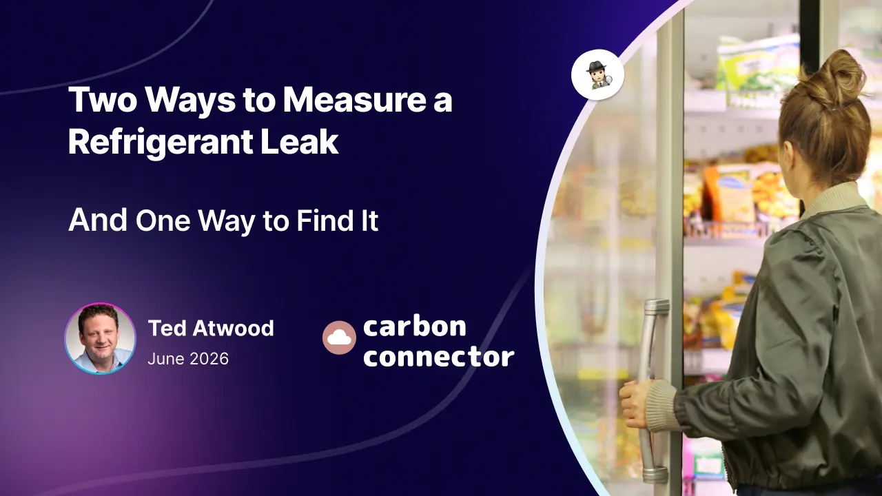
Two Ways to Measure a Refrigerant Leak and One Way to Find It
Every refrigerant leak detection system is trying to answer the same question: Is there refrigerant gas in the air, and where? It sounds simple. It is not.
Refrigerant is invisible, often heavier than air, and it moves — sinking, pooling, riding the airflow off an evaporator fan, dispersing toward the nearest open door.
To find it, you have to measure its concentration in space, over time. And the moment you say it that way, a quieter and more important question emerges:
How densely are you actually measuring?
Not how sensitive the sensor is. Not how many decimal places are on the readout.
How much of the real, three-dimensional refrigerated space is being sampled, how often, and how close to where the gas actually is.
That is the question the market has mostly stopped asking, and it is the question that separates the two dominant philosophies in this industry.
📌 Ready to take the blindfold off your maintenance teams?
Shop our distributed leak detection solutions now and pinpoint leaks instantly.
TL;DR
Refrigerant leak detection equipment consists of specialized tools used by HVAC/R technicians to identify, trace, and pinpoint escaping refrigerant gases from air conditioning or cooling systems.
This article explores the main types of refrigerant leak detection equipment and how their underlying measurement philosophies determine how much of a space is actually protected — and whether a leak can be located, not just detected.
The equipment splits into two roles.
Handheld (portable) detectors
They are the sniffers a technician carries to trace and pinpoint a leak once on site — essential for the repair, but only working when someone is there to use them.
Fixed-mounted (stationary) detectors
They are installed permanently to monitor a space continuously, day and night, whether or not anyone is present.
This piece focuses on the fixed-mounted, continuous-monitoring category — and the three competing philosophies within it: centralized aspirated (tube-based) sampling, distributed in-situ sensing, and indirect, data-driven detection.
What it covers
The main types of refrigerant leak detection equipment and how each one measures; the measurement philosophies behind them; the real-world pros and cons of each approach, including failure modes most spec sheets omit; and practical selection criteria — coverage, response time, the ability to locate a leak, and compliance.
Who it’s for
HVAC/R professionals, refrigeration contractors, facility and energy managers, supermarket and cold-storage operators, and sustainability or compliance leads responsible for refrigerant management.

Why it matters
Leaks drive up refrigerant and energy costs, create safety risks, and carry real regulatory exposure under EPA Section 608 and the AIM Act.
But if we strip away all the other reasons, one of the most important is that emergency repairs related to leaks are very common, which places extreme pressure on a workforce already stretched thin.
Choosing the right detection equipment is now a question of helping the workforce, meeting compliance, efficiency, cost control, and safety — not just hardware.
Two Refrigerant Leak Detection Methods, One Question
The first philosophy is centralized aspiration.
One high-quality sensor (typically a non-dispersive infrared (NDIR) cell) lives in a central station, usually installed in or near the machine room or a utility area within the building.
A network of small-diameter tubes (quarter-inch is standard) runs out to each monitored zone. A pump draws air back through those tubes, one zone at a time, and presents each sample to the single shared sensor in sequence.
Bacharach’s multi-zone platforms are the most widely deployed example of this approach. The design logic is to bring the air to the sensor.
The second philosophy is distributed in-situ sensing.
Instead of one sensor reading many places through tubing, you place many fixed sensors directly in the spaces you care about — each one living permanently in the air it monitors, reading continuously, and easier for technicians to operate because every device stays in place and reports on its own.
This is the architecture behind the AKO program. The design logic is the inverse: put the sensor in the air.
It is worth being precise about what is not the difference here. The sensing element itself can be excellent in either design — both philosophies can and do use NDIR.
The argument is not “their sensor is bad”.
A superb sensor at the end of a tube is still a superb sensor.
The argument is architectural: one excellent sensor can only be in one place at one time. Everything that follows flows from that single constraint.
The double meaning of density
Here is why “density” is the right lens, and not just a clever word. It carries two meanings, and both matter.
The first is the density of measurement — how richly you sample space and time.
A centralized system samples one point per zone (wherever the tube end happens to be), and only when that zone’s turn comes up in the cycle.
A distributed system samples the whole occupied volume of each zone continuously. One is sparse in space and sparse in time. The other is dense in both.
The second is the density of the gas — the physical behavior of the refrigerant itself.
R-404A is roughly three times heavier than air. It does not politely wait at the ceiling for a tube to find it. It sinks, it stratifies, it collects in low and enclosed pockets, and it dilutes rapidly as it travels.
This is where sparse measurement runs into trouble, because the two densities interact badly: the gas behaves in three dimensions, and the centralized tube is sampling a single point in that volume.
The whole comparison comes down to this: the physical density of the gas demands a high density of measurement.
The centralized philosophy cannot supply it, not because the engineering is poor, but because the architecture forbids it.
📌 Ready to take the blindfold off your maintenance teams?
Shop our distributed leak detection solutions now and pinpoint leaks instantly.
Where Centralized (Aspirated) Leak Detection Struggles in Commercial Refrigeration
Look at what the centralized, tube-based philosophy has to overcome, and notice that none of these are manufacturing defects. They are consequences of the design.
Spatial sparsity
A quarter-inch tube draws air from the immediate vicinity of its opening.
Tube manufacturers don’t publish an “effective sampling area per port,” and there’s a reason for that — doing so would quantify exactly how small it is.
You don’t need their number to see the constraint, though; their own installation guidance reveals it.
The instruction is always to place the port as close as possible to the likely leak source.
If a single port genuinely monitored the whole zone, placement proximity wouldn’t matter. The fact that it matters is the admission.
This is also where the marketing and the physics quietly part ways.
A centralized system advertises “16-zone coverage” on the strength of having a tube end in each of sixteen zones.
But a port in a zone is not monitoring a zone. It’s a single straw sampling one small patch of a large, three-dimensional space, and only when its turn comes around.
Calling that “zone coverage” is like calling yourself Batman because you own one flashlight. You’ve got a piece of the kit. You do not have the capability the name implies.
Temporal sparsity
Because one sensor serves many zones, the system rotates through them.
The default zone-hold interval on common controllers is fifteen minutes, and contractors rarely change defaults. With sixteen zones, a full cycle can run up to four hours.
A leak that develops, peaks, and partially dissipates inside a defrost cycle (in a zone that isn’t currently being sampled) can come and go without ever reaching the sensor on its turn, even though finding leaks early matters because low charge can reduce cooling performance, overwork compressors, and create compliance problems.
Dilution in transit
The manufacturer’s own documentation acknowledges that if the tube end is not at the exact point of the leak, the system reads a diluted concentration.
The sample you measure is not the sample at the source; it’s whatever survived the trip down the tube.
A blockage you may never see
Those tubes run through cold, dirty, humid spaces and collect what’s in the air: dust, oil mist, condensation, and in freezer applications, ice.
A partially blocked tube throttles the draw, so you read a diluted, delayed version of reality.
A fully blocked tube takes its zone offline outright.
Fixed refrigerant leak detection equipment provides continuous monitoring and can automatically trigger alarms when a leak occurs, while technicians still rely on a range of proven techniques for detecting refrigerant leaks in HVAC systems to pinpoint and verify the source.
The dangerous part is that neither failure announces itself — the pump keeps running, the cycle keeps turning, and a zone you believe is protected may not have been sampled in weeks.
A break you may never see
A single store can carry well over a thousand feet of tubing, routed through ceilings, over racks, and behind cases.
Over time, those runs get crushed, kinked, knocked loose at fittings, or nicked during unrelated work.
A pinhole lets the pump quietly pull in ambient air and dilute whatever the zone actually holds; a full disconnection simply erases the zone.
Electronic leak detectors typically use a pump to pull surrounding air over a sensing element and trigger an alarm when refrigerant is present.
And once again, the system tends to keep reporting “normal” for a zone it is no longer truly sampling.
The silent failure is the worst kind, because nothing prompts anyone to go check.
One flood distorts what comes next
When a real, high-concentration event is finally drawn in, it doesn’t pass through and vanish.
Residual gas lingers in the shared line and at the detector, so the next zone in the rotation can read high even when it’s perfectly clean — a false alarm manufactured by the previous zone’s air.
Trying to cure the latency by speeding up the cycle only deepens this: faster rotation leaves less time to purge, and contamination bleeds forward from one reading into the next.
You cannot shorten the wait without corrupting the data.
And there’s a human cost stacked on top: operators who get burned by phantom highs learn to distrust the alarms, which is exactly the wrong instinct to build into a leak-detection program.
Calibration and a single point of failure
Calibrating a centralized station has always been complicated by the plain logistics of getting calibration gas to the right place at the right time.
And beneath all of it sits one pump and one sensor serving every zone.
When that shared heart falters, the whole installation goes with it — not one zone, all of them at once.
Portable electronic detectors are still useful for narrowing leaks to specific regions or components of HVAC systems and are often paired with bubble confirmation, which improves reliability and gives technicians a reliable way to verify the source; a well-chosen mix of HVAC leak detector tools helps ensure that once a zone alarms, every likely joint and fitting can be checked quickly.
📌 Stop guessing where the leak is.
Contact us today to map your store’s actual coverage and see the data-driven difference.
Where dense measurement answers
Now run the same list against the distributed philosophy, and watch each problem dissolve into the architecture.
Spatial sparsity disappears because the sensor is in the zone, reading the air around it rather than waiting for gas to migrate down a tube.
A fixed system still works alongside portable leak detector tools used to confirm the source. In open areas (a wet wall, an open meat or deli case, a machine room), a sensor in free air responds across a wide radius in every direction.
The contrast is stark when you make it physical: a single in-place sensor monitors the air across a roughly fifty-foot reach, in every direction at once, while a tube port samples a patch you could cover with one hand.
One is watching the room. The other is watching a keyhole and calling it the room.
Temporal sparsity disappears because every sensor reads continuously.
There is no cycle, no queue, no waiting for a turn. Infrared detectors measure changes in infrared light absorption and are less prone to false alarms from moisture or oil.
Heated diode detectors use a heated sensor to ionize refrigerant molecules and trigger an alarm.
For halogen-based refrigerants, technicians commonly use heated diode or infrared sniffers as the refrigerant leak detector of choice.
Under a conservative assumption (call it a full minute for circulating air to carry gas to a sensor mounted in the airstream), distributed sensing is on the order of 240 times more responsive than a four-hour default cycle.
The headline math is larger; the conservative floor alone is decisive, and it rests on a number printed in the competing system’s own manual.
Dilution, shared-line contamination, and pump failure simply don’t exist as categories, because there is no tube and no shared central instrument.
And maintenance changes character entirely when each sensor is an independent, in-place unit rather than a node on a fragile pneumatic network.
Bubble solutions remain a cost-effective way to verify larger leaks, and ultrasonic tools can help when detecting leaks in noisy spaces, especially when combined with specialized HVAC leak detector tools that can see or hear leaks technicians might otherwise miss.
Knowing a leak exists is not the same as finding it
There’s a third approach worth putting on the table, because it’s the one generating the most excitement right now: indirect, data-driven detection.
Instead of sensing gas in the air at all, these platforms watch the behavior of the refrigeration system itself (pressures, superheat, runtime, mass balance) and infer from the pattern that charge is being lost somewhere.
It’s genuinely good technology. As an early-warning layer, it can flag a slow loss long before anyone walking the floor would notice, and it does it without placing a single sensor in the cases.
But look closely at the question it answers. It tells you that you probably have a leak. It does not tell you where.
It’s Marco Polo. You close your eyes, you call out, and somewhere across the pool a voice calls back. You know someone’s there.
You lunge toward the sound, and half the time you come up with a handful of water.
The signal is real, but it’s a direction at best, never a location. A data-driven platform can tell you a rack is losing charge. It cannot tell you it’s the third fitting on the B-coil in the dairy walk-in.
Someone still has to go find that: blindfold on, hands out.
And here is the part the industry consistently underprices: the cost of a refrigerant leak was never known until it exists. It’s in the search.
The expensive hours are the technician walking the store with a sniffer, stretching service time across case after case, and trying to save labor while chasing a problem the data has confirmed is real but won’t pin down.
Indirect detection, for all its sophistication, hands that technician a blindfold and a general heading.
Even a direct system that only alarms (“gas, somewhere in zone 9, sometime in the last four hours”) leaves most of the search intact.
Dense, in-place measurement is what takes the blindfold off.
Because a sensor lives in the zone and reads continuously, the system doesn’t just announce that a leak exists, it reports which device detected it, how the concentration built over time, and what the profile looks like.
The technician arrives already knowing the zone, the device, and the leak signature before the pinpointer ever comes out of the truck, which gives the user simpler controls in the field and faster support for field teams.
The search collapses from “somewhere in the store” to “right here.”
That is the difference between detecting a leak and getting to one, and it runs on the same measurement density that made the detection trustworthy in the first place.
You cannot localize what you sampled once, through a tube, from an unknown point. You can localize what you measured densely, in place, the entire time.
From concentration to consequence in refrigeration systems
There is a final reason density of measurement matters, and it’s the one that turns detection into something a business can act on.
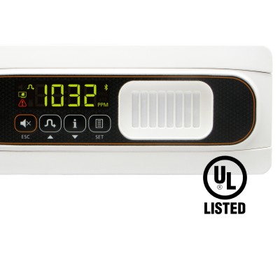
A concentration reading (say, 420 parts per million (ppm) of R-404A in Zone 9) is only a number.
To make a decision, you have to convert it into mass: how many pounds of refrigerant are actually escaping.
That conversion is straightforward physics — the measured ppm, multiplied by the volume of the space, multiplied by the density of the specific refrigerant, yields actual mass lost.
AKO’s volumetric methodology does exactly this, turning a ppm spike into projected annual loss, percentage of charge at risk, the carbon footprint of the leak in CO2e, and ultimately the dollar cost of inaction; with continuous monitoring, catching issues early also helps lower energy costs and improve system efficiency.
A centralized monitoring system for HVAC assets supports that process through real-time data collection, helping teams plan more effectively and reduce downtime.
But notice the dependency.
That calculation is only trustworthy if you actually know the concentration in the volume, which means you have to be measuring densely, in the space where the gas is, without readings being distorted by local temperature or humidity conditions.
A single diluted sample drawn through a tube from an unknown point in the zone cannot anchor a volumetric calculation; you’d be multiplying a guess by a guess, which also weakens energy efficiency decisions.
Dense measurement isn’t just better detection.
It’s the precondition for converting detection into accountability — the compliance record, the emissions ledger, the verified pounds saved, and the asset-level trail supported by asset tagging that identifies each physical unit by location and status.
Effective asset tagging also improves inventory visibility and reduces the risk of lost or misidentified assets.
The honest version
None of this means centralized aspiration was a mistake.
It was the right answer for the problem it was designed around: a confined machine room, a few discrete points, short tube runs, an era when one good sensor was expensive, and tubing was cheap.
In a space like that, most of the failure modes above barely register — the runs are short, the zones are few, and the fouling, dilution, and cross-contamination that plague a sprawling sales-floor install never get the chance to accumulate.
In that context, bringing the air to the sensor made complete sense.
A port in a zone isn’t monitoring a zone — it’s one straw sampling one small patch of a very large space.
Calling that coverage is like calling yourself Batman because you own one flashlight.
The modern refrigerated retail floor is a different problem.
It is large, open, full of distributed cases and walk-in coolers, and governed by tightening emissions rules — EPA Section 608 and the AIM Act now impose real leak-rate thresholds, repair deadlines, and recordkeeping obligations on high-GWP refrigerants like R-404A, increasing the value of robust, layered refrigerant leak detection strategies that can stand up under regulatory and operational pressure.
It is operated by teams that need to act on what they find, not just be told that something, somewhere, tripped an alarm four hours ago.
The problem changed. The architecture that fits it changed with it.
📌 Ready to take the blindfold off your maintenance teams?
Shop our distributed leak detection solutions now and pinpoint leaks instantly.
When searching for leak detection solutions, what you should really be asking (?)
If you’re evaluating leak detection, the sensitivity spec on the datasheet is the wrong place to start.
Ask the density questions instead, and recognize that closing the trust gaps between technology, field teams, and management is just as important — a point explored further in holistic approaches to closing trust gaps in refrigerant leak detection:
What happens to every other zone when one pump, one sensor, or one tube fails?
Would a 24/7 refrigerant leak detection service layer help you see and respond to those failures before they become compliance events?
Will the system support natural refrigerants such as carbon dioxide in supermarkets, grocery stores, and other food retailers, and fit the realities of each building where food is stored, sold, and protected for customers?
Can your leak detection choices improve energy efficiency and help you reduce costs over time, especially when paired with integrated technology-and-service programs designed to solve refrigerant leaks end to end?
How much of each zone’s actual volume is being sampled, not “is there a port in the zone,” but how much of the air in it?
How long can a leak develop in any one zone before the system is guaranteed to read it?
When the system flags a leak, does it tell you where (which device, which zone, what the leak looks like over time) or only that something, somewhere, is wrong?
Does the reading reflect the gas at the source, or whatever survived dilution on the way to a shared sensor?
Can the system convert a concentration into pounds lost and carbon emitted — and is the measurement dense enough to make that conversion honest, ideally supported by Leak Detection as a Service models that turn raw readings into continuous, managed outcomes?
Answer these questions, and the choice between the philosophies stops being a feature comparison. It becomes obvious.
The gas is dense, three-dimensional, and impatient.
The only measurement philosophy that matches it is one that is equally dense — present everywhere, all the time, where the air actually is.
Bring the air to the sensor, or put the sensor in the air. Once you’ve watched how refrigerant actually behaves, there isn’t really a debate.
Frequently Asked Questions
How does refrigerant leak detection work?
Refrigerant leak detection works by measuring the concentration of refrigerant gas in the air, usually in parts per million (ppm).
Systems do this one of three ways: they draw air samples through tubing back to a central sensor, place fixed sensors directly inside each refrigerated zone, or infer leaks indirectly from refrigeration-system performance data; fixed systems can also continue operating accurately through sudden changes in temperature or humidity when the sensor is designed for those conditions, rather than being thrown off by a sudden shift.
The practical differences come down to how much of the space is monitored, how often, and whether the system can actually locate the leak.
What is the difference between aspirated and fixed refrigerant detection?
Aspirated (sample-draw) detection uses one central NDIR sensor and a network of small tubes that pull air from each zone in sequence; depending on likely leak points, the tubing may be routed near components such as a condenser or valves, monitoring a single point at a time.
Fixed, distributed detection places an individual sensor in each zone that reads continuously.
Aspirated systems cover less of the space, less often, and through a shared line; distributed systems monitor every zone simultaneously and can identify which sensor detected the leak.
Why do refrigerant leak detectors give false alarms?
False alarms are common in centralized aspirated systems because every zone shares one sample line and one detector.
A high reading in one zone can leave residual gas in the line, contaminating the next zone’s sample and producing a false high on a zone that is actually clean.
Indirect, data-driven platforms also flag performance anomalies that turn out not to be leaks, which is why many operators turn to proactive refrigerant leak detection platforms with predictive analytics to separate real events from noise and support better dispatch decisions.
Distributed fixed sensors avoid shared-line cross-contamination because each sensor reads only its own air, and higher-end fixed sensors are designed for superior performance and more reliable detection in changing conditions.
Can a refrigerant leak detection system tell you where the leak is?
It depends on the architecture. Indirect, data-driven systems usually cannot — they confirm a leak exists somewhere but not its location, leaving technicians to search the store.
Centralized systems can name a zone at best, and only if they catch the leak during that zone’s cycle.
The AKO and Carbon Connector approach is built to pinpoint it: distributed sensors capture how the concentration builds over time, patented analytics profile the leak’s characteristics, and human-in-the-loop review isolates the likely source, so the technician arrives knowing the device, the zone, and the signature of the leak before the search even begins.
The same system can also trigger automated actions, such as closing valves once a leak crosses a defined threshold, to limit loss while the repair is arranged, aligning with best-practice refrigerant leak management that treats every pound saved as both an environmental and financial win.
How often do refrigerant detection systems need calibration?
Most refrigerant gas sensors need periodic calibration (commonly once a year) using a known calibration gas.
Centralized systems are harder to keep calibrated because a single shared sensor and long tube runs complicate getting calibration gas to the right point.
Distributed sensors are calibrated or swapped one at a time, and a single failed unit affects only its own zone rather than taking the whole store offline.
What are the main types of refrigerant leak detection?
There are three.
- Centralized aspirated detection uses one sensor and sample tubing routed to each zone.
- Distributed fixed detection places a sensor in every zone, monitoring continuously.
- Indirect, data-driven detection infers a likely leak from refrigeration-system data without sensing gas in the air at all.
They differ most in measurement density — how much of the space is watched, how continuously, and whether the leak can be pinpointed.
Is refrigerant leak detection required by law?
For many commercial refrigeration systems, yes.
Under EPA Section 608 of the Clean Air Act and the newer AIM Act, operators face leak-rate thresholds, mandatory repair timelines, and recordkeeping obligations for high-GWP refrigerants such as R-404A; in commercial refrigeration used by supermarkets and medium temp applications, continuous monitoring supports safer operation and compliance, especially in any building serving food storage or retail where emissions and safety records must be maintained.
Continuous monitoring helps operators catch leaks early, document compliance, and quantify emissions in CO2e — turning a regulatory burden into a managed, auditable record and supporting comprehensive refrigerant leak emission reduction strategies across an entire portfolio.
See what dense measurement looks like in your stores
Carbon Connector and AKO USA help refrigeration operators move from “an alarm went off somewhere” to a complete, verifiable picture — pounds leaked, charge at risk, carbon emitted, and the action that closes the loop.
If you’re rethinking how you detect, locate, and document refrigerant loss, we’ll map your actual coverage and show you the difference in plain numbers.
Start the conversation, or see how field teams capture every refrigerated asset with Tag Wizard.
📌 Ready to take the blindfold off your maintenance teams?
Shop our distributed leak detection solutions now and pinpoint leaks instantly.